How to Avoid Thermal Bridging in Home Construction: A Forensic
The evolution of North American residential construction has reached a critical juncture where the mere addition of insulation is no longer sufficient to meet high-performance energy targets. For decades, the industry focused on “nominal R-value”—the theoretical thermal resistance of a material in a laboratory setting. How to Avoid Thermal Bridging in Home Construction. However, as building codes tighten and the pursuit of “Net Zero” and Passive House standards moves from the fringe to the mainstream, architects and builders are confronting the pervasive reality of the “Thermal Bridge.” This phenomenon occurs when a highly conductive material, such as a wood stud, a steel lintel, or a concrete floor slab, creates a direct path for heat to bypass the insulation layer.
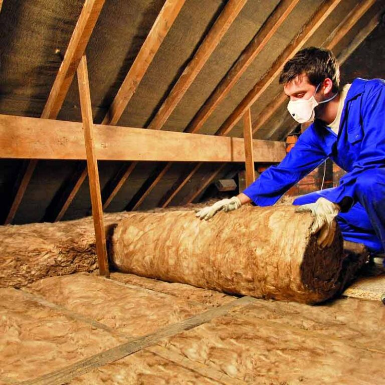
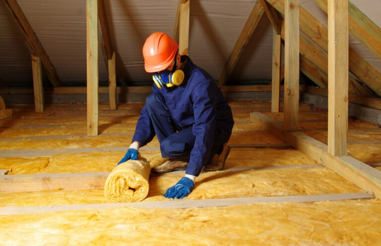
To understand the systemic impact of these thermal shortcuts is to recognize that a house is not a series of isolated components, but a singular thermodynamic vessel. When a wall is insulated with R-20 fiberglass batts between 2×6 studs spaced 16 inches apart, the “effective” R-value of the assembly is significantly lower than the rating on the packaging. The wood studs, which have an R-value of approximately 1.2 per inch, act as highways for energy. In a typical home, these structural members can account for 25% of the wall’s surface area. Without intervention, this “structural radiator” compromises the comfort of the occupants, increases operational costs, and, most critically, creates localized cold spots that invite condensation and biological growth.
This study provides a definitive framework for navigating the complexities of thermal mitigation. We move beyond surface-level energy efficiency tropes to analyze the systemic drivers of heat transfer—from the geometry of the “rim joist” to the role of “psi-values” in modern energy modeling. By dismantling the mechanics of continuous insulation and advanced framing, we establish a methodology for the architectural stewardship of the home. This is an examination of the residence as a high-performance vessel, engineered to eliminate the invisible leaks that have historically plagued the American building envelope.
Understanding “how to avoid thermal bridging in home construction”
In the professional architectural and building forensic spheres, the mandate to learn how to avoid thermal bridging in home construction is regarded as an exercise in “Envelope Decoupling.” It is a multi-perspective challenge that requires the specifier to reconcile the structural requirements of a building with the laws of thermodynamics. A common misunderstanding among observers is that thermal bridging is only a concern in extreme climates. In reality, the “Delta-T” (temperature difference) between the interior and exterior environments drives heat transfer in all regions. In hot climates, thermal bridges act as conduits for cooling loss, while in cold climates, they are the primary sites for “ghosting”—the accumulation of dust on cold wall sections caused by temperature-driven air movement.
Oversimplification risks are highest when a project focuses solely on the “opaque” wall sections. While insulating the wall studs is vital, the most significant thermal bridges often occur at the “geometric” junctions: where the wall meets the roof, the corners of the building, and the interface between the foundation and the first floor. Effectively determining how to avoid thermal bridging in home construction for a specific project requires a calculation of “Linear Thermal Transmittance” (psi-values). This involves a shift from one-dimensional R-value thinking to a three-dimensional analysis of how heat “wraps” around corners and penetrates structural connections.
Furthermore, a sophisticated approach must address the “Hygrothermal Paradox.” As we increase insulation levels to mitigate thermal bridging, we inadvertently make the exterior sheathing colder during the winter. If the thermal bridge is not properly managed through exterior continuous insulation, the interior moisture—driven by high-pressure indoor air—can condense on the cold surfaces of the structural members. The “best” plan is one that recognizes thermal bridging mitigation not just as an energy-saving measure, but as a critical durability strategy for preventing structural rot and mold.
Systemic Evolution: From Mass Walls to Thermal Breaks
The history of thermal management has transitioned through three distinct “Ages of Construction.” The First Age (Pre-1900s) was the Age of Thermal Mass. Stone and brick buildings relied on the sheer thickness of the walls to buffer temperature swings. While these buildings had high “Thermal Lag,” they lacked modern insulation, and their structural connections were essentially massive thermal bridges.
The Second Age (1920s–1990s) was the Age of the Cavity Wall. The introduction of light-frame wood and steel construction allowed for the placement of insulation within the wall. However, this era largely ignored the thermal conductivity of the frame itself. The R-value was seen as a “filling,” and the studs were simply accepted as “un-insulated” gaps in the thermal blanket.
The Third Age—the one we currently occupy—is the Age of the “Wrapped Envelope.” This era is defined by the move toward “Continuous Insulation” (CI). We have moved beyond “fill” strategies toward a model where a layer of rigid foam, mineral wool, or wood fiber board is applied to the outside of the structural frame. This evolution is driven by the maturation of building codes (such as IECC 2021) which now mandate thermal bridge mitigation in many climate zones through prescriptive “R+R” (Cavity + Continuous) requirements.
Conceptual Frameworks and Mental Models of Heat Flow
To evaluate thermal bridging with editorial and technical rigor, professionals utilize specific mental models:
-
The “Thermal Break” Model: This views the house as a circuit. Just as an electrical circuit requires an insulator to stop current, a thermal circuit requires a “break” in the conductive path. This model prioritizes materials with low conductivity (like structural thermal breaks or foam) at every point where a structural member penetrates the insulation.
-
The “Clear Wall” vs. “Real Wall” Framework: This distinguishes between the laboratory R-value of a wall section and its performance in the field once studs, headers, and plates are accounted for. It forces the builder to design for the “Real Wall” effective R-value.
-
The “Isotherm” Mapping Concept: This treats the house as a temperature gradient. By visualizing the “Isotherms” (lines of constant temperature), the builder can identify where the lines “compress” at a structural member, indicating a high-velocity heat leak.
-
The “Radiator Effect” Logic: This recognizes that a steel beam or concrete balcony extending from the interior to the exterior is not just a leak; it is a radiator that actively pumps energy out of (or into) the building.
Primary Technology Categories: Advanced Framing and Continuous Barriers
Achieving an envelope free of thermal shortcuts requires a tiered approach to structural design and material selection.
Comparative Taxonomy of Mitigation Solutions
| Strategy | Mechanical Approach | Primary Benefit | Implementation Complexity |
| Continuous Insulation (CI) | Exterior Rigid Board | Eliminates nearly all stud bridges. | High (Requires cladding adjustment) |
| Advanced Framing (OVE) | 24″ O.C. Stud Spacing | Reduces stud count by 20-30%. | Low (Requires engineering) |
| Staggered Studs | Alternating Studs | Breaks the direct path through the wall. | Medium (Deepens the wall) |
| Double Stud Walls | Parallel Framed Walls | Creates a massive thermal break. | High (Large footprint) |
| Structural Thermal Breaks | Thermal Shims / Pads | Isolates balconies and lintels. | High (Engineered components) |
| Exterior Wood Fiber | Vapor-Open Rigid Board | Carbon-neutral thermal break. | Medium (Specific fasteners) |
Realistic Decision Logic
The choice of typology is often a function of “Assembly Depth.” In an urban infill project where every inch of floor space is valuable, Continuous Insulation on the exterior is the gold standard, as it provides a radical thermal break without thickening the interior wall footprint. Conversely, for a custom “Passive House” in a cold climate, the logic often favors Double Stud Walls, as they allow for 12+ inches of cellulose insulation while completely decoupling the interior and exterior frames.
Detailed Real-World Scenarios and Decision Logic How to Avoid Thermal Bridging in Home Construction
The Multi-Story Cantilever (Coastal/Modern)
-
The Challenge: Steel beams extending outward to support a balcony create a massive thermal bridge that causes cold floors and condensation indoors.
-
The Strategy: Installing “Structural Thermal Break” modules (e.g., Schöck Isokorb) at the building envelope line.
-
The Logic: These modules use high-strength stainless steel and high-density insulation to maintain structural integrity while providing a 90% reduction in thermal conductivity.
The “Rim Joist” Retrofit (Northeast)
-
The Challenge: The area where the floor joists sit on the foundation is often a “web” of thermal bridges and air leaks.
-
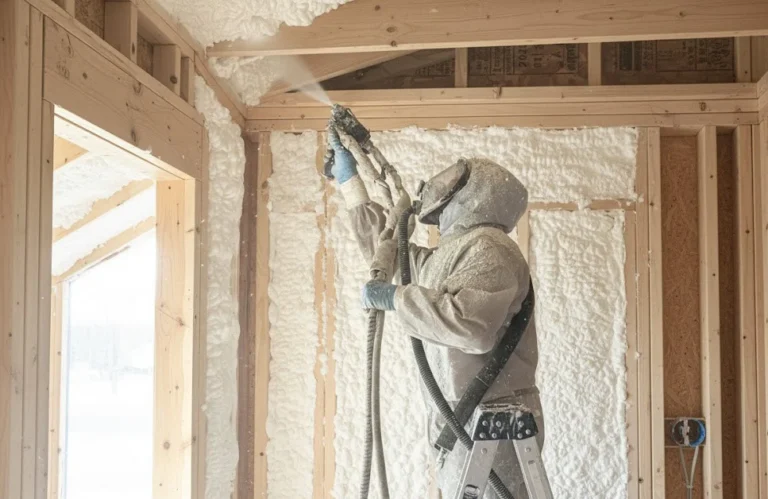
The Strategy: Applying 2 inches of closed-cell spray foam or rigid foam “cut-and-cobble” at every joist bay.
-
The Logic: The foam acts as both a thermal break and an air seal, preventing the “convective loop” that typically strips heat from the basement and first floor.
The Advanced Framing Custom Build (Midwest)
-
The Challenge: Reducing wood use and increasing insulation volume in a standard 2×6 wall.
-
The Strategy: Switching to 24-inch on-center spacing, two-stud corners, and ladder blocking for interior walls.
-
The Logic: By removing “extra” wood that isn’t structurally necessary, the builder increases the “Cavity-to-Stud Ratio,” allowing for more insulation and fewer thermal bridges.
Planning, Cost Architecture, and Resource Dynamics
The economic profile of thermal bridge mitigation is defined by the “Value of Permanence.” Generally, the upfront cost for continuous insulation is 15-25% higher than standard framing, but this is a one-time investment that pays dividends for the life of the building.
Range-Based Resource Allocation (Per 2,000 Sq. Ft. Envelope)
| Component | Standard Grade (No CI) | High-Performance (CI) | Forensic/Passive Grade |
| Insulation Material | $6,000 | $12,000 (Rigid Foam) | $22,000 (Wood Fiber/CC) |
| Framing Labor | $8,000 | $7,000 (Advanced) | $12,000 (Double Stud) |
| Specialized Fasteners | $200 | $1,500 (Long screws) | $3,500 (Thermal Pads) |
| Diagnostic (Modeling) | $0 | $1,200 (BEopt/WUFI) | $4,000 (Detailed Psi) |
| Total (Est.) | $14,200 | $21,700 | $41,500 |
The Variability Factor: The “Hidden Payback” is the downsizing of the HVAC system. When you understand how to avoid thermal bridging in home construction, you reduce the “Peak Load” of the building, often allowing for a 1-ton reduction in AC sizing, which can save $3,000–$5,000 in mechanical costs immediately.
Tools, Strategies, and Support Systems
Executing a thermal-bridge-free vision requires a shift from “Construction” to “Mechanical Assemblies”:
-
Thermal Bridge Modeling Software (THERM): A free tool from LBNL that allows architects to simulate heat flow through complex junctions.
-
Infrared Thermography: Used in cold weather to “see” the thermal bridges as bright glowing lines on the exterior of the house.
-
Low-Conductivity Fasteners: Glass-fiber reinforced polymer (GFRP) brick ties and thermally broken cladding clips (e.g., Cascadia Clips).
-
Structural Insulated Panels (SIPs): A factory-built “sandwich” of foam and OSB that inherently reduces thermal bridging by eliminating most studs.
-
Heated-Platen Cutters: For creating precise grooves in exterior foam for electrical or plumbing runs without compromising the continuous layer.
-
Blower Door Testing: While primarily for air sealing, it helps identify where thermal bridges are exacerbating convective air leaks.
-
Z-Girting Decouplers: Plastic or rubber shims that isolate metal cladding supports from the structural wall.
Risk Landscape: Failure Modes and Compounding Hazards
The pursuit of the “Perfect Envelope” is not without its “Compounding Risks.”
-
“The Cladding Sag Failure”: Applying 4 inches of rigid foam without a structural plan for attaching the siding. The weight of the cladding can cause the fasteners to bend, leading to “cladding creep.”
-
“The Vapor Barrier Trap”: Using an impermeable exterior foam in a cold climate without sufficient R-value. If the foam isn’t thick enough, the interior sheathing hits the dew point, and moisture is trapped by the foam, leading to mold.
-
“The Foundation Bypass”: Insulating the walls perfectly but failing to insulate the “slab edge.” Heat simply migrates down the wall and out through the uninsulated concrete foundation.
-
“The Fastener Bridge”: Using thousands of steel screws to attach exterior foam. If not accounted for, the cumulative thermal bridge of the steel screws can reduce the foam’s effectiveness by 15-20%.
Governance, Maintenance, and Long-Term Adaptation
A thermally broken building is a “Precision Instrument” that requires a documented “Operational Protocol.”
-
The “Envelope Governance” Cycle: Every 10 years, the exterior cladding should be inspected for “fastener distress.” In systems with heavy exterior insulation, monitoring for signs of siding movement is a key maintenance trigger.
-
The “Isotherm Monitoring”: In high-performance builds, wireless sensors (like HOBO loggers) can be placed inside the wall at a known thermal bridge to ensure the temperature never drops below the dew point.
-
Governance Checklist:
-
[ ] Verify “Cladding Clip” torque every 5 years (commercial).
-
[ ] Audit roof-to-wall junctions for “shadowing” or signs of ice dams.
-
[ ] Inspect exterior foam for “termite tunnels” (borate-treated foam is the primary governance).
-
[ ] Ensure HVAC “Dehumidification Mode” is active to manage the tight envelope’s interior humidity.
-
Measurement, Tracking, and Empirical Evaluation
-
Leading Indicators: The “Calculated Psi-Value.” A top-tier design should target linear thermal transmittance of less than 0.01 W/mK for major junctions.
-
Lagging Indicators: Total energy consumption in kWh, specifically focusing on the “Heating/Cooling Base Load.”
-
Qualitative Signals: “Surface Temperature Uniformity.” A successful mitigation strategy ensures that the corner of a room is the same temperature as the center of the wall.
-
Documentation Example: A “Thermal Bridge Atlas”—a collection of infrared photos and THERM models provided to the owner to prove the envelope’s continuity.
Common Misconceptions and Oversimplifications
-
Myth: “Fiberglass batts stop thermal bridging.” Correction: Batts only insulate the space between the bridges. They do nothing to stop the heat flowing through the studs.
-
Myth: “Wood doesn’t bridge heat because it’s natural.” Correction: While wood is less conductive than steel, it is still 4x more conductive than modern insulation. It is a major bridge.
-
Myth: “Double-pane windows eliminate the window bridge.” Correction: The window frame is usually the bridge. High-end plans require “thermally broken” frames or over-insulating the frame with exterior foam.
-
Myth: “You only need to insulate the north side.” Correction: Thermal bridging is a function of the entire envelope; heat is indifferent to compass direction.
-
Myth: “Continuous insulation causes the wall to rot.” Correction: Only if the “Vapor Profile” is ignored. CI actually keeps the wall warmer and drier if designed correctly.
-
Myth: “A thermal bridge is just a small leak.” Correction: In a highly insulated house, a single significant thermal bridge (like a concrete balcony) can account for 20% of the total heat loss.
Ethical, Practical, or Contextual Considerations
The endeavor to master how to avoid thermal bridging in home construction is ultimately an ethical calculation of “Resource Resilience.” In an era of grid volatility, a thermally broken home acts as a “Battery of Comfort.” During a power outage in a winter storm, a home with a continuous thermal break will maintain habitable temperatures for days, whereas a standard-framed home will become dangerously cold within hours. Furthermore, by reducing the operational carbon of the building, we are mitigating the long-term environmental debt of our construction practices. The transition to “Low-Conductivity” architecture is not a luxury; it is a necessary adaptation to a resource-constrained future.
Synthesis: The Future of the Disconnected Envelope
The trajectory of the global building industry is moving toward “Total Envelope Decoupling.” We are seeing the rise of “Vacuum Insulated Panels” (VIPs) and “Aerogel” shims that can provide R-20+ in a fraction of an inch. However, the core of this experience remains the building science. No amount of advanced material science can compensate for a lack of forensic detail at the corners and junctions.
To successfully manage a modern thermal environment is to embrace the “Physics of Separation.” It is a rejection of the “stud-and-fill” mentality in favor of a legacy-based approach where the structure and the thermal layer are treated as two distinct, non-interacting systems. By prioritizing “Continuous Resistance” and “Structural Isolation,” the builder ensures that the residence remains a stable, filtered, and resilient sanctuary for a century, rather than a high-energy liability.